

Limit switches as sensors? Turns out the oldest tech in the box is still the most dependable.
When I first started tinkering with ESP32 projects, I chased after the latest flashy sensors—ultrasonic, infrared, capacitive touch. But it wasn’t until I dusted off an old limit switch from my parts bin that I realized some of the best solutions are the simplest. Limit switches as sensors may seem like relics from a bygone era, but they offer unmatched reliability and straightforward integration with the ESP32.
In the world of Free and Open Source Software and hardware, where accessibility and durability matter most, this humble component shines. It’s not about reinventing the wheel but empowering makers and developers with proven tools that work anywhere, anytime.
If you’re ready to embrace practical, no-nonsense sensor setups that your ESP32 will thank you for, keep reading—this guide shows you exactly how to use limit switches as sensors the right way.

How It Works
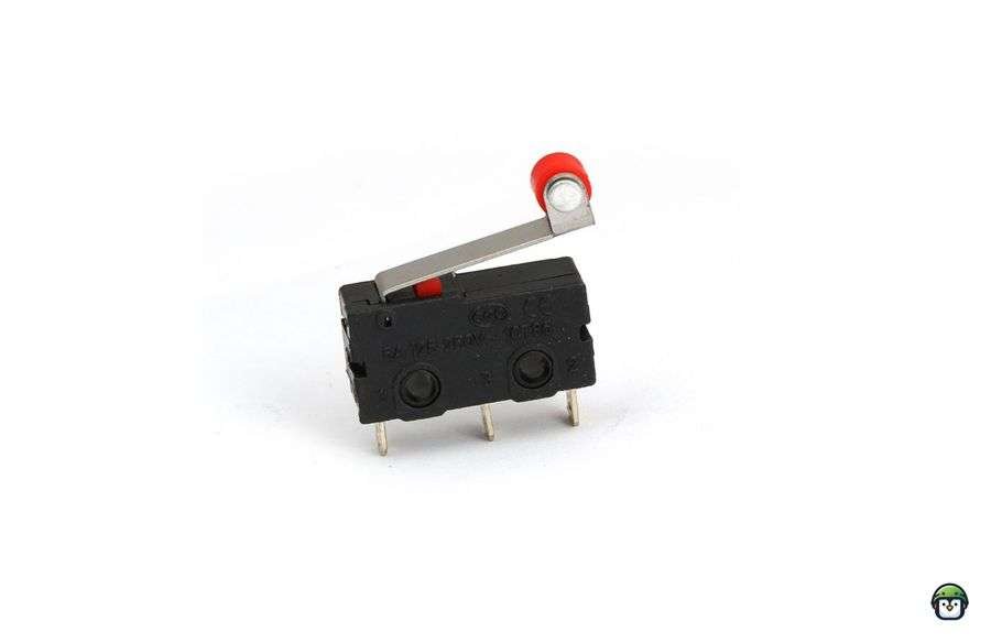
Limit switches typically contain a mechanical actuator that responds to external pressure or movement. When the actuator is pressed, it either closes or opens a circuit, depending on the design of the switch.
- Normally Closed (NC) Limit Switch: In contrast, a normally closed limit switch has a closed circuit by default, and pressing the actuator opens the circuit, signaling that contact has been lost or the limit has been exceeded.
- Normally Open (NO) Limit Switch: In its default state, the circuit remains open (off). When the switch is pressed, it closes the circuit, sending a signal to the system indicating that the limit has been reached or contact has been made.
Wiring Limit Switches as Sensors to ESP32
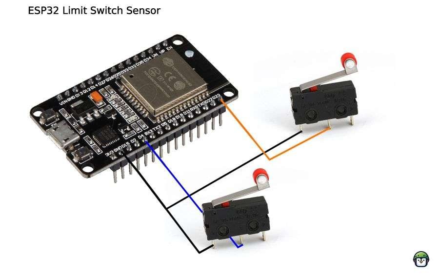
Before diving into applications, it’s essential to understand how to wire a Limit Switch as Sensor to the ESP32. The simplest setup involves connecting the limit switch to one of the ESP32’s GPIO (General Purpose Input/Output) pins.
- Limit Switch as Sensor Connections:
- One terminal of the limit switch connects to a digital GPIO pin on the ESP32 (e.g., GPIO 14).
- The other terminal of the limit switch connects to GND (Ground) or 3.3V, depending on the type of switch (normally open or normally closed).
- If you’re using a normally open (NO) Limit Switch as Sensor, the circuit will only be closed when the switch is activated (pressed or triggered by movement).
- Pull-up/Pull-down Resistor:
Most digital inputs on the ESP32 are configured with an internal pull-up or pull-down resistor, which can be enabled in software. For a normally open switch, you’ll want to enable the internal pull-up resistor to ensure the input pin is pulled to HIGH when the switch is not triggered.
Like what you’re reading?
Help keep DevDigest
free and caffeine-powered
—buy me a coffee on Ko-fi.
Basic Limit Switches as Sensors Functionality with ESP32
Limit Switches as Sensors are typically used in two ways: either as an input trigger to signal the microcontroller or as part of a feedback system for controlling motor or actuator movement. In the ESP32, you can monitor the state of a Limit Switch as Sensor through its GPIO pin. When the Limit Switch as Sensor is pressed or triggered, it will either send a LOW signal (in a normally open setup with a pull-up resistor) or a HIGH signal (in a normally closed setup with a pull-down resistor).
Here is a simple example of how to read the state of a Limit Switch as Sensor in MicroPython:
from machine import Pin
import time

# Define the GPIO pin for the limit switch
limit_switch1 = Pin(23, Pin.IN, Pin.PULL_DOWN)  # GPIO23 with internal pull-up resistor
limit_switch2 = Pin(4, Pin.IN, Pin.PULL_DOWN)  # GPIO4 with internal pull-up resistor

while True:
    if limit_switch1.value() == 1:  # The switch is triggered
        print("Limit switch 1 activated")
    else:
        print("Limit switch 1not activated")

    if limit_switch2.value() == 1:  # The switch is triggered
        print("Limit switch 2 activated")
    else:
        print("Limit switch 2 not activated")

    time.sleep(0.1)
In this example, GPIO 14 is used to read the state of the Limit Switch as Sensor. The code checks if the switch is activated by detecting whether the value is LOW (indicating that the switch has been triggered). The program then prints a message to the console based on the switch’s state.
· · ─ ·𖥸· ─ · ·
Debounce Handling for Limit Switches
Mechanical switches don’t make a clean open/close contact instantly. They “bounce” for a few milliseconds, creating multiple signals that can confuse your ESP32 code.
Why debounce matters:
Without debounce, a single press might register as multiple presses.
Two approaches:
- Hardware debounce: Add a small capacitor or use an RC circuit to smooth the signal physically.
- Software debounce: Use a short delay or timer in your code to ignore signals within a certain threshold after the first detection.
Here’s a simple software debounce example in Arduino code:
const int limitSwitchPin = 14;
int lastSwitchState = HIGH;
unsigned long lastDebounceTime = 0;
unsigned long debounceDelay = 50;

void setup() {
  pinMode(limitSwitchPin, INPUT_PULLUP);
  Serial.begin(115200);
}

void loop() {
  int reading = digitalRead(limitSwitchPin);
  if (reading != lastSwitchState) {
    lastDebounceTime = millis();
  }

  if ((millis() - lastDebounceTime) > debounceDelay) {
    if (reading == LOW) {
      Serial.println("Limit switch pressed!");
    }
  }

  lastSwitchState = reading;
}
This debounce logic lets you rely on the switch signal without false triggers, making your ESP32 sensor setup rock solid.
· · ─ ·𖥸· ─ · ·
Practical Use Cases for Limit Switches as Sensors
Limit Switches as Sensors have various applications in ESP32 projects, providing feedback for automated systems. Below are a few examples where Limit Switches as Sensors can play a vital role:
- Motorized Doors:
Limit Switches as Sensors can detect when a motorized door reaches its fully open or closed position, preventing over-travel and protecting the motor from damage. The ESP32 can control the motor while using Limit Switches as Sensors to halt movement when the door reaches the desired position. - Robotic Arms:
In robotic arm applications, Limit Switches as Sensors are used to detect the extreme positions of the arm’s joints. When the arm reaches the limit, the switch activates, allowing the ESP32 to stop the movement or change its direction. - Elevator Systems:
Limit Switches as Sensors are commonly used in elevator systems to detect the top and bottom floor positions. The ESP32 can use these sensors to control the elevator’s stopping mechanism, ensuring it doesn’t exceed the desired position. - 3D Printers:
Limit Switches as Sensors are often used in 3D printers to detect the position of the print head or bed. The ESP32 can use the Limit Switch as Sensor to calibrate the printer’s movements, ensuring accurate prints every time.
· · ─ ·𖥸· ─ · ·
Benefits of Using Limit Switches as Sensors with ESP32
Using Limit Switches as Sensors in ESP32 applications brings several advantages:
- Reliability: Limit Switches as Sensors are mechanical components that provide a simple yet highly reliable way to detect position. They are less prone to failure compared to optical or magnetic sensors in certain environments.
- Cost-Effective: Limit Switches as Sensors are inexpensive and readily available, making them a budget-friendly choice for many automation and control projects.
- Ease of Use: Integrating Limit Switches as Sensors with the ESP32 is straightforward, requiring only basic wiring and simple programming to implement.
- Versatility: Limit Switches as Sensors can be used in various applications, from robotics to home automation systems, providing position feedback for more accurate control.
· · ─ ·𖥸· ─ · ·
Why Limit Switches as Sensors Still Matter for ESP32 Builders
To wrap up, limit switches as sensors prove that sometimes the oldest tech in the box is still the most dependable. They deliver reliable, tactile feedback with minimal fuss, perfect for anyone—from beginners to seasoned developers—who values simplicity, cost-effectiveness, and robustness in their ESP32 projects.
By embracing these time-tested components within the open-source spirit, you empower yourself to build smarter, more resilient hardware without breaking the bank or drowning in complexity.
Want to keep unlocking practical hardware hacks and real-world insights? Subscribe to my newsletter at samgalope.dev/newsletter and join a community passionate about FOSS-powered innovation.
Like what you’re reading?
Help keep DevDigest
free and caffeine-powered
—buy me a coffee on Ko-fi.
Leave a Reply