Servo motors are widely used in robotics and automation for their ability to provide precise control over angular positions. However, ensuring smooth and accurate movements requires careful management of PWM (Pulse Width Modulation) signals. In this article, we will explore how to achieve ESP32 Servo Motor Smooth Movement using MicroPython and the ESP32’s high-resolution PWM capabilities.
Whether you’re designing a robotic arm, a pan-tilt camera system, or animatronics, smooth servo control is essential for professional and polished results. With its powerful features and affordability, the ESP32 is an ideal microcontroller for implementing seamless servo motor movements. This guide will provide step-by-step instructions, sample code, and tips for optimizing your servo-driven projects.
Table of Contents
What is PWM and Its Role in ESP32 Servo Motor Smooth Movement?
PWM, or Pulse Width Modulation, is a technique that controls the position of a servo by varying the width of electrical pulses. The ESP32 excels in this area due to its capability to generate precise and stable PWM signals. Smooth movements are achieved by gradually changing the pulse width, ensuring that the servo transitions gently between positions without abrupt stops or jitters.
Related:
Wiring Setup for ESP32 Servo Motor Smooth Movement
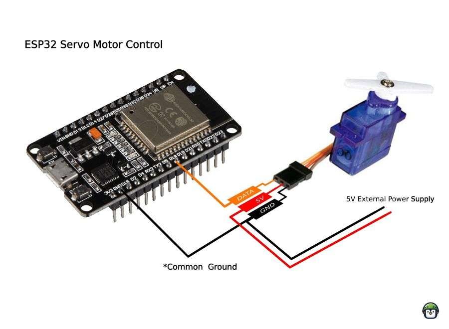
- Materials Needed:
- ESP32
- Servo motor (e.g., SG90 or MG995)
- External 5V power source (if required)
- Breadboard and jumper wires
- Connections:
- Servo signal → GPIO18
- Power → 5V external source
- Ground → Common ground for ESP32 and servo
Coding for ESP32 Servo Motor Smooth Movement
Here’s a MicroPython script:
from machine import Pin, PWM
import time

servo = PWM(Pin(18), freq=50)

def set_angle(angle):
    duty = int((angle / 180) * 102 + 26)
    servo.duty(duty)

def smooth_move(start, end, step=1, delay=0.02):
    if start < end:
        for angle in range(start, end + 1, step):
            set_angle(angle)
            time.sleep(delay)
    else:
        for angle in range(start, end - 1, -step):
            set_angle(angle)
            time.sleep(delay)

while True:
    smooth_move(0, 180)
    smooth_move(180, 0)
Understanding the Formula
1. Understanding Servo Motor Control with PWM

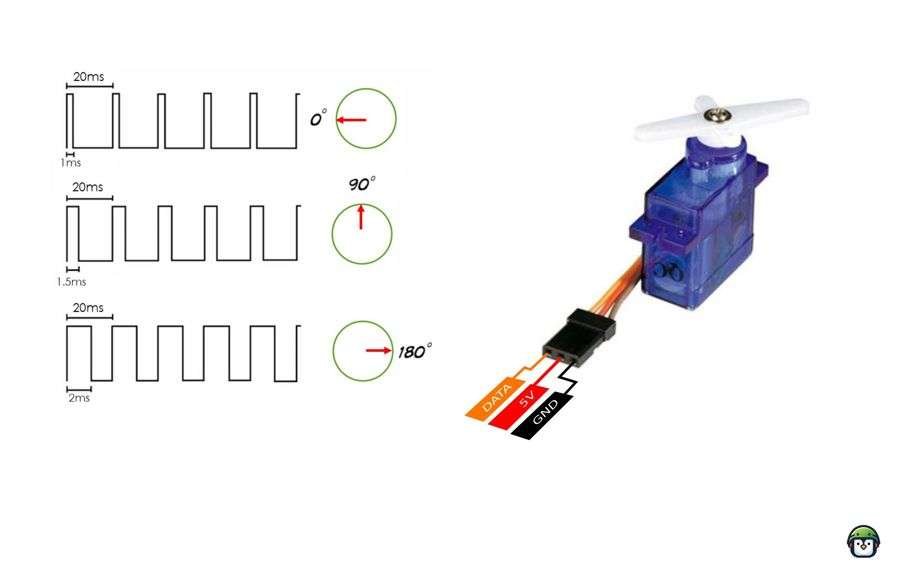
Servo motors are controlled by sending a PWM signal where the pulse width determines the servo’s angular position. The relationship between the pulse width and the angle is typically:
- Pulse Width Range: Usually between 1 ms (minimum position) and 2 ms (maximum position) for a standard servo.
- PWM Frequency: Most servos use a frequency of 50 Hz, corresponding to a period of 20 ms (1/50 Hz).
Within the 20 ms period:
- A 1 ms pulse (5% duty cycle) moves the servo to 0°.
- A 2 ms pulse (10% duty cycle) moves the servo to 180°.
- Intermediate positions are achieved by varying the pulse width proportionally between 1 ms and 2 ms.
2. Breaking Down the Formula
a. angle / 180
- This part normalizes the given angle (0° to 180°) into a proportional value between
0and1.- For example:
angle = 0°→0 / 180 = 0angle = 90°→90 / 180 = 0.5angle = 180°→180 / 180 = 1
- For example:
b. * 102
- The ESP32’s PWM output uses a range of duty cycles corresponding to the servo’s pulse width.
- For a 50 Hz frequency:
- A 1 ms pulse corresponds to approximately 26/1024 duty cycle.
- A 2 ms pulse corresponds to approximately 128/1024 duty cycle.
Thus, the full range of duty cycles for the servo (from 0° to 180°) spans 102 steps (128 - 26 = 102).
angle / 180 * 102scales the normalized angle (0 to 1) to the servo’s duty cycle range (0 to 102).- Example:
angle = 0°→0 * 102 = 0angle = 90°→0.5 * 102 = 51angle = 180°→1 * 102 = 102
- Example:
c. + 26
- This offsets the calculated duty cycle to start at 26, ensuring the minimum pulse width corresponds to 1 ms (0° position).
- Example:
angle = 0°→0 + 26 = 26angle = 90°→51 + 26 = 77angle = 180°→102 + 26 = 128
- Example:
d. int()
- Since the PWM duty cycle needs to be an integer, the
int()function ensures the result is rounded down to the nearest whole number.
3. Final Range of Duty Cycles
- For
angle = 0°:duty = 26→ Corresponds to a 1 ms pulse. - For
angle = 180°:duty = 128→ Corresponds to a 2 ms pulse. - For intermediate angles, the formula linearly interpolates the duty cycle.
4. Why This Formula is Important
This formula ensures smooth and accurate control of the servo motor by mapping the input angle (0–180°) to the appropriate PWM duty cycle. It’s tailored for:
- A 50 Hz PWM frequency.
- Standard servo pulse widths of 1–2 ms.
- The ESP32’s duty cycle resolution.
Optimizing ESP32 Servo Motor Smooth Movement
- Use smaller steps and shorter delays for finer control.
- Ensure a stable power supply to avoid performance issues.
- For multi-servo setups, consider the PCA9685 driver module for extended PWM control.
Applications of ESP32 Servo Motor Smooth Movement
- Robotic arms for precise joint movement.
- Pan-tilt camera mounts for smooth tracking.
- Animatronic displays with lifelike motion.
Conclusion
Achieving ESP32 Servo Motor Smooth Movement is crucial for creating professional and reliable robotic systems. By leveraging the ESP32’s PWM capabilities, you can implement smooth and seamless servo control in your projects. From animatronics to advanced robotics, mastering this skill will unlock endless possibilities for innovation.
The combination of accurate PWM signals, stable power supply, and optimized coding practices ensures superior performance. With the techniques covered in this guide, you’re ready to bring your servo-driven projects to life with precision and grace.


Leave a Reply