

I was toggling LEDs with delays—until Timers on ESP32 made it all feel like overkill.
I used to think toggling LEDs with delay() was just how it’s done. It worked—until it didn’t. The moment I added a second LED with a different blink rate, everything broke. My code became spaghetti, the LEDs flickered out of sync, and my ESP32 felt more like an Arduino on NyQuil.
That’s when I discovered something game-changing: Timers on ESP32. Instead of blocking the main loop or writing messy conditionals, I started assigning precise tasks to hardware timers. Suddenly, my LEDs blinked independently, my code stayed clean, and I could finally start thinking like a systems designer—not just a desperate tinkerer.
If you’ve ever felt the pain of delay() locking up your projects, or you want a scalable way to control multiple LEDs (and more), this guide will show you how to do it right—with real-time control, clean logic, and full respect for the power of open hardware.
👉 Let’s ditch the delay and do this the FOSS way.

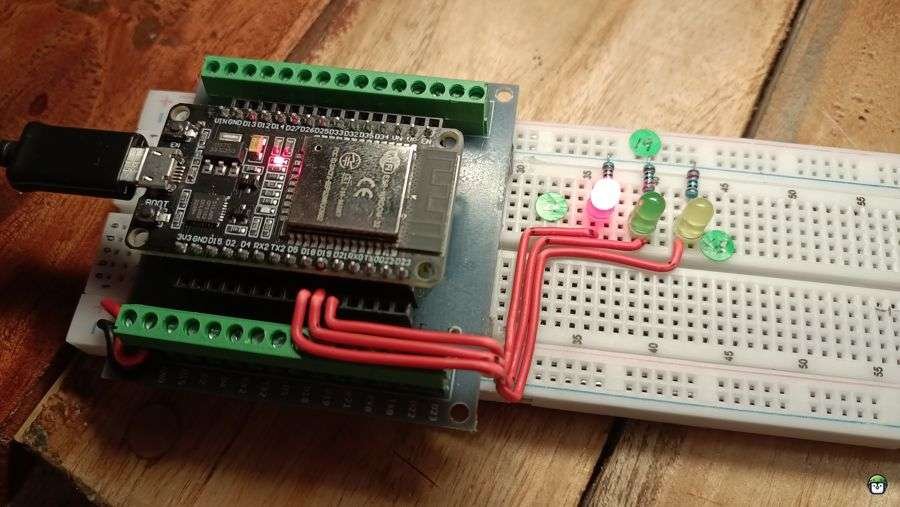
Wiring the Circuit for Multiple LEDs with Timers on ESP32
To get started with controlling multiple LEDs with timers on ESP32, you need to wire the LEDs to specific GPIO pins. This section will describe the wiring for each LED and how to connect them to the ESP32.
Components Needed:
- 3 LEDs
- 3 Resistors (220Ω each)
- Breadboard and jumper wires
- ESP32 board
Wiring Steps:
- LED Connections:
- Pin 18 (GPIO18): Connect the longer leg (anode) of the first LED to GPIO18 on the ESP32. Connect the shorter leg (cathode) of the LED to one end of a 220Ω resistor.
- Pin 21 (GPIO21): Connect the longer leg (anode) of the second LED to GPIO21 on the ESP32. Connect the shorter leg (cathode) of the LED to one end of another 220Ω resistor.
- Pin 19 (GPIO19): Connect the longer leg (anode) of the third LED to GPIO19 on the ESP32. Connect the shorter leg (cathode) of the LED to one end of the last 220Ω resistor.
- Ground Connections:
- Connect the other end of each 220Ω resistor to GND (ground) on the ESP32. This ensures that the LED circuit is complete and the current can flow properly.
By using resistors, we protect the LEDs from excessive current, ensuring they function properly and don’t burn out.
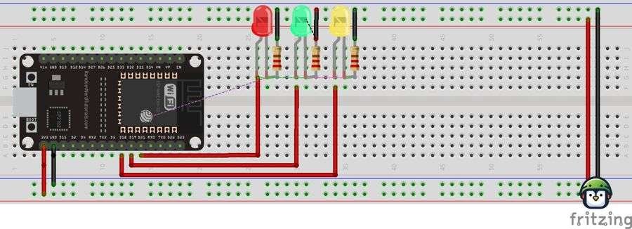
Circuit Diagram
Below is a rudimentary circuit diagram illustrating the setup:
Implementing Timers for Multiple LEDs
You can create individual timer functions for each LED. These timers will toggle the LED’s state (on or off) at different intervals, giving you control over their blink patterns. Here’s how you can implement this in MicroPython:
from machine import Pin, Timer

# Define the pins for the LEDs
led_pin_18 = Pin(18, Pin.OUT)
led_pin_21 = Pin(21, Pin.OUT)
led_pin_19 = Pin(19, Pin.OUT)

# Counters for controlling the blink intervals
counter_18 = 0
counter_21 = 0
counter_19 = 0

# Function to control LED on pin 18
def led_blink_18(t):
    global counter_18
    counter_18 += 1
    if counter_18 >= 5:  # Blink every 500 ms
        led_pin_18.value(not led_pin_18.value())
        print("LED 18 is ON" if led_pin_18.value() else "LED 18 is OFF")
        counter_18 = 0

# Function to control LED on pin 21
def led_blink_21(t):
    global counter_21
    counter_21 += 1
    if counter_21 >= 3:  # Blink every 300 ms
        led_pin_21.value(not led_pin_21.value())
        print("LED 21 is ON" if led_pin_21.value() else "LED 21 is OFF")
        counter_21 = 0

# Function to control LED on pin 19
def led_blink_19(t):
    global counter_19
    counter_19 += 1
    if counter_19 >= 7:  # Blink every 700 ms
        led_pin_19.value(not led_pin_19.value())
        print("LED 19 is ON" if led_pin_19.value() else "LED 19 is OFF")
        counter_19 = 0

# Set up the timers for each LED
t1 = Timer(1)
t2 = Timer(2)
t3 = Timer(3)

t1.init(period=100, mode=Timer.PERIODIC, callback=led_blink_18)
t2.init(period=100, mode=Timer.PERIODIC, callback=led_blink_21)
t3.init(period=100, mode=Timer.PERIODIC, callback=led_blink_19)
How It Works
- Pin Setup: Each LED is connected to a unique GPIO pin on the ESP32.
- Timer Control: Each LED has a corresponding timer with a specific blink interval. For example, one LED blinks every 500 ms, another every 300 ms, and the third every 700 ms.
- Timer Callbacks: The callback functions toggle the state of each LED independently, using counters to control the timing without blocking other operations.
- Independent Operation: This method allows each LED to blink at its own rate, making it suitable for projects where multiple indicators or status lights are needed.
· · ─ ·𖥸· ─ · ·
Why Use Timers for Multiple LEDs?
Using multiple timers for LEDs on ESP32 offers several benefits:
- Non-blocking: Each LED operates independently without blocking other operations on the ESP32.
- Efficiency: The timer interrupts are lightweight and don’t consume excessive CPU resources, making them ideal for long-running applications.
- Flexibility: You can easily adjust the blink intervals for each LED based on your project requirements.
· · ─ ·𖥸· ─ · ·
Conclusion: Timers That Work, Projects That Scale
Why Timers on ESP32 Should Be Your Default for LED Control
Here’s the truth: delay() works—until you want to do anything else. Timers on ESP32 free you from lockstep logic and open the door to smoother, more reliable control for LEDs, motors, buzzers, and beyond. Whether you’re building a smart light system or a multi-tasking microcontroller app, hardware timers give you the precision and flexibility your project deserves.
More importantly, using timers forces you to think modularly—like the engineer you’re becoming.
If this helped clear up the mystery behind timers, or saved you from another delay-riddled meltdown, I share more practical deep dives like this every week.
👉 Subscribe here for FOSS-based ESP32 hacks, real-world circuit builds, and open automation wins:
https://www.samgalope.dev/newsletter/
Let’s make microcontrollers smarter—starting with us.
Like what you’re reading?
Help keep DevDigest
free and caffeine-powered
—buy me a coffee on Ko-fi.
Leave a Reply