

ESP32 wiring seemed easy… until I powered it backwards and smoked my voltage regulator.
I was confident—maybe too confident. I had my ESP32, a breadboard, some jumper wires, and a vague memory of a YouTube tutorial. “How hard could ESP32 wiring be?” I thought. Then I reversed the power and watched a tiny puff of smoke escape from the voltage regulator. That distinct electronic-burn smell still haunts me.
For a lot of us in the FOSS space, learning by breaking is almost a rite of passage. But that doesn’t mean you have to make the same mistakes. Whether you’re prototyping a sensor network, building a smart home project, or teaching kids how to blink their first LED, solid wiring habits are what keep your board alive—and your workflow sane.
In this guide, I’ll walk you through practical, beginner-proof ESP32 wiring strategies, the logic behind each pin, and a few tricks that even seasoned devs miss.

Know Your Pins: ESP32 Pinout Explained for Beginners
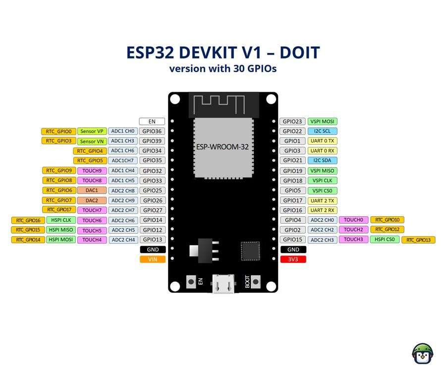
The ESP32 is a powerful board—but only if you know which pins do what. Here’s a quick breakdown of the essential ones:
| Pin | Function | Notes |
|---|---|---|
| VIN / 5V | Input power (for regulator) | Accepts 5V from USB or battery |
| 3V3 | Regulated 3.3V output | Power your sensors and peripherals |
| GND | Ground | Connect all grounds here |
| GPIO0–GPIO39 | General Purpose I/O | Not all pins are equal—some are input-only or reserved |
| EN | Enable (Reset) | Pulled high to keep the board running |
| GPIO34–GPIO39 | Input only | Use for sensors, not LEDs or buttons |
| GPIO6–11 | Flash SPI | Avoid using these—they’re reserved for internal flash |
| GPIO12 | Boot-sensitive | Avoid pulling high during boot unless needed |
When wiring, always check a trusted ESP32 pinout diagram (e.g., for the DEVKIT v1) to avoid connecting to restricted pins. Bookmark one, print it, or tape it to your desk—it’ll save your board more than once.
· · ─ ·𖥸· ─ · ·
Your First Safe Circuit – LED with Resistor
💬 Subheading Suggestion:
💡 First Circuit: Wiring an LED with a Resistor (and Why It Matters)
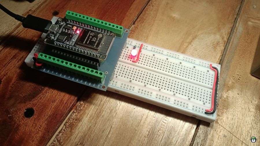
Before you start wiring sensors or displays, let’s test your setup with a simple LED circuit—the “Hello World” of electronics.
You’ll need:
- 1 x LED
- 1 x 220Ω resistor
- 2 x jumper wires
- Breadboard
- ESP32 board
Wiring Steps:
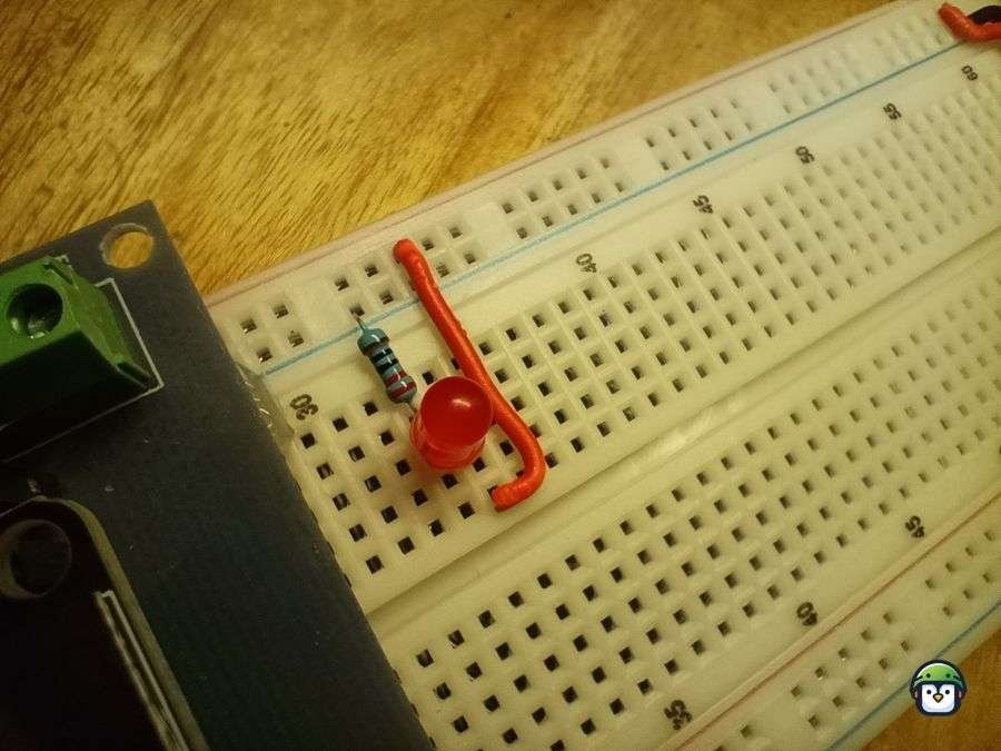
- Connect the short leg (cathode) of the LED to GND on the ESP32.
- Connect the long leg (anode) to one end of the resistor.
- Connect the other end of the resistor to GPIO 2 (or any safe digital pin).
- Upload this MicroPython or Arduino sketch:
from machine import Pin
import time

led = Pin(2, Pin.OUT)

while True:
    led.value(1)
    time.sleep(0.5)
    led.value(0)
    time.sleep(0.5)
Why the resistor? LEDs need current limiting. Without it, you risk damaging both the LED and your ESP32’s GPIO pin.
· · ─ ·𖥸· ─ · ·
Best Practices for ESP32 Wiring
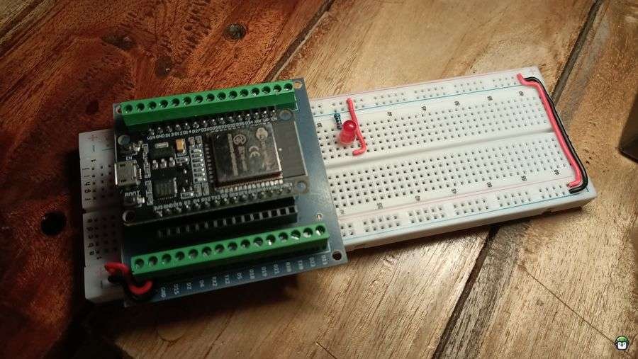
Use Breadboards for Prototyping:
Breadboards are ideal for creating temporary, solder-free circuits. They allow for easy adjustments without permanent connections, making them a great tool for beginners.
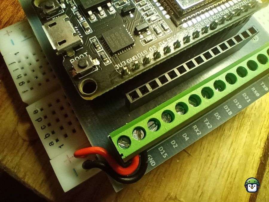
Double-Check Connections:
Always ensure that connections are secure and that no pins are shorted. Incorrect wiring can damage your ESP32 or other components.
Use External Power Supplies:
The ESP32 is powered by 3.3V, but some peripherals might require different voltages. Be sure to use external power sources when necessary to avoid overloading the ESP32’s onboard regulator.
By following these basic wiring techniques and best practices, you’ll be able to build a variety of projects with your ESP32. As you gain experience, you’ll discover even more advanced wiring techniques and how to incorporate a wider range of components into your designs.
· · ─ ·𖥸· ─ · ·
ESP32 Wiring Different Components
- LEDs: Connect the positive (longer) leg of the LED to a GPIO pin, and the negative (shorter) leg to a resistor, which then connects to the ground (GND). This simple connection allows you to control the LED with basic code.
- Sensors: For an analog sensor like a temperature sensor, you would connect the output pin to one of the ESP32’s analog input pins. Many modern sensors use I2C or SPI communication, so you’ll wire the SDA (data) and SCL (clock) pins from the sensor to the ESP32’s corresponding I2C pins.
- Motors: When working with motors, you’ll typically need a motor driver or H-bridge circuit. This is necessary because the ESP32 cannot provide enough current directly to power motors. The motor driver connects to the ESP32’s digital I/O pins to control the motor’s speed and direction.
· · ─ ·𖥸· ─ · ·
Conclusion: Clean Wiring, Clear Thinking
Learn It Once, Wire It Right Every Time
ESP32 wiring isn’t just about getting power and ground in the right places. It’s about understanding how pins behave, why certain voltages matter, and how to keep your circuits modular, readable, and repairable—especially when things go wrong. By wiring with intention (and a little paranoia), you avoid common pitfalls and unlock the full potential of your board without expensive mishaps.
And let’s face it—nothing builds confidence like powering up a circuit and having it just work.
If you found this guide helpful, I share hands-on tutorials like this every week—always FOSS-friendly, always grounded in real-world experience.
👉 Subscribe here to get ESP32 guides, open-source hacks, and maker wins straight to your inbox:
https://www.samgalope.dev/newsletter/
Let’s build smart. Let’s build free.
Like what you’re reading?
Help keep DevDigest
free and caffeine-powered
—buy me a coffee on Ko-fi.
Leave a Reply